Motion Technology
1. Drive Technologies
Servo Motors
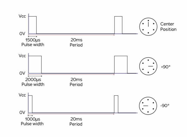
A servo motor is a rotation or translational motor which is powered by a servo amplifier. They allow for precise control in terms of angular position, acceleration and velocity. It consists of a motor and an encoder for determining rotational speed of the motor, it uses a positive feedback system to control the motion and final position of the shaft.
Servo motors are self-contained electrical devices that use a series of drive gears for exact movement. When applied to CNC, servo motors are used to control the position of the cutting implement. They are also used to control the rotational velocity of grinding and milling machines.
Due to their compact form factor, they have less inertia compared to induction motors. The synchronous motor can accelerate and decelerate to and from its rated speed. They are ideal for packaging applications. These low inertia motors provide precise, coordinated motion when combined with EtherCAT Motion Control. From tracking to sorting and forming, this adaptable setup works well in almost any part of the packaging line.
Author: Wikimedia user Hforesti. Unedited Image.
Benefits:
- High accuracy and repeatability.
- Adjustable speeds.
- Full torque can be delivered at zero speed.
- Position holding without torque loss.
- Can operate in closed-loop with servo drives.
Disadvantages:
- More expensive than stepper motors.
- Susceptible to overheating and thermal runaway.
- Require tuning and calibration for feedback loop.
- Peak torque is limited to a 1% duty cycle.
Applications:
Wafer Handling and Positioning: Precision servo motors are used in wafer transport systems and positioning stages during semiconductor fabrication, ensuring accurate movement and alignment of semiconductor wafers.
Photolithography: These motors provide precise control in optical alignment systems within photolithography equipment, essential for the patterning of integrated circuits on silicon wafers.
Etching and Deposition: Precision servo motors are used in etching and thin-film deposition processes to control the movement of robotic arms and substrate holders, ensuring sub-micron accuracy in layer fabrication.
Inspection and Metrology: In inspection tools and metrology systems, these motors enable fine adjustments of scanning heads and microscopes for detailed analysis of wafers and microstructures.
Stepper Motors
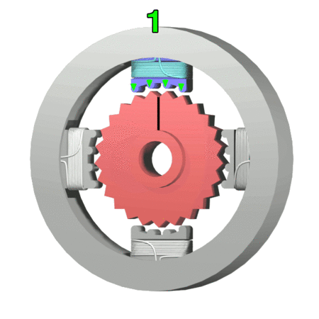
Stepper motors operate by accurately synchronizing with the pulse signal output from the controller to the driver, achieving highly accurate positioning and speed control. They feature high torque and low vibration at low speeds. These systems are ideal for applications requiring quick positioning in a short distance. A stepper motor rotates with a fixed step angle. Highly accurate open-loop control can be performed due to the mechanical structure within the motor.
Stepper motors are very robust and reliable since the control of rotation and speed is achieved without using electrical components such as encoders.
Benefits:
- Low-cost alternative to servo motors.
- Open-loop control.
- Have a long duty life.
- Strong holding torque due to magnetic locking.
Disadvantages:
- Prone to overheating due to maximum current draw even at hold positions.
- Difficult to operate at high frequencies.
- Low torque at high speeds.
- Lose accuracy when micro stepping at high resolution.
- Prone to stalling at certain frequencies due to resonant vibrations.
Applications:
- Semiconductor Manufacturing: Used for wafer positioning, alignment and handling specifically for applications requiring step and hold.
- Medical Devices: Used in infusion pumps and surgical robots for precise movements during procedures.
- 3D Printing: Control the motion of the print head and platform for detailed 3D printing applications.
Voice Coil Actuators
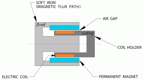
Voice coil actuators consist of a current carrying coil interacting with a permanent magnet. The cylindrical coil is connected to the power supply with a non-magnetic center pole. The current running through the coil creates a magnetic field which interacts with the field established by the permanent magnet.
The displacement is proportional to the current in the coil, and this proportionality allows for accurate positioning. Additionally, reversing the current flow in the coil causes a reversal in the interaction with the permanent magnets field. This allows for the voice coil to move in both directions.
Voice coil actuators are designed for use in applications requiring positioning with high speed or acceleration. A voice coil converts electrical signals directly into linear magnetic force, providing much higher purity of motion compared to DC motors.
Benefits:
- High precision: Ranges from 20 nanometers to 1 micron.
- High speed: Can perform at high-speed motion profile loops up to 1 KHz in open-loop and 125 Hz in closed-loop.
- Low hysteresis: Majority of hysteresis comes from connection cables.
- No cogging or commutation due to brushless design.
Disadvantages:
- Short travel range: Less than 25 mm.
- Low force output: Usually does not exceed 10 N.
- Relatively high cost.
- Heat generation when used continuously.
Applications:
- Medical Devices: Voice coil actuators are used in surgical robots, patient positioning systems, and diagnostic equipment, providing precise and rapid movements.
- Optical Equipment: These actuators are essential in camera autofocus systems, laser scanners, and microscopes for fast and accurate adjustments of lenses and mirrors.
- Aerospace: In aerospace applications voice coil actuators are used for precise control of components such as satellite antennas, flight control systems, and optical systems.
Flex-Hinge Piezo
Flex-hinge piezo actuators use piezoceramic in combination with a flexible compliant structure to produce precise, small-scale displacement. The piezo ceramic (PZT) deforms when an electric field is applied to it. The piezoceramic is bonded to a flexible hinge to leverage the motion produced by the voltage. These actuators are commonly used for fine positioning applications where smooth, continuous motion is required.
Benefits:
- High Precision: Sub-nanometer resolution.
- Smooth motion.
- Stable and predictable.
Disadvantages:
- Limited motion range compared to other actuator types: limited to a few mm.
- Performance is sensitive to extreme temperature changes.
- Requires specialized electronics with very low electrical noise.
- Heavy loads limit high speed performance.
Applications:
- Semiconductor Manufacturing: Flex-hinge piezo actuators are used for optical metrology and fine positioning tasks for semiconductor advanced packaging.
- Space communication: Piezo tip-tilt actuators are used for precision control of satellite antennas, optical systems and flight control surfaces.
- Automation: Flex-hinge piezo actuators enable high-speed positioning, fine adjustments, and operational efficiency in applications like robotic arms, automated handling, and assembly processes.
Piezo Stepper Motor
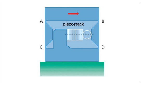
Piezo Stepper Motors use multiple actuators that both expand and bend sideways as voltage is applied. These actuators act in pairs to grip a longitudinal runner and move it forward. The first pair of actuators then releases the runner and the next pair engages. Due to the walking type of motion they exhibit, the actuators of a piezo stepper motor are often referred to as “legs.” Each pair of actuators moves a few microns per cycle at a very high frequency to achieve thousands of “steps” per second. This allows these motors to have very long travel ranges compared to flex-hinge piezo actuators.

Author: LaurensvanLieshout. Unedited Image.
Benefits:
- Long travel range: Up to several hundred mm.
- Resolution: Extremely high resolution, typically in the micrometer to sub-micrometer range.
- Low vibration and high resolution/ repeatability compared to mechanical solutions.
- Self-locking at rest.
- Do not generate heat.
- Smaller and simpler to integrate on top of a linear bearing compared to a piezoelectric stage.
Disadvantages:
- Higher cost than traditional piezo actuators.
- Lower maximum holding force, velocity and frequency.
- Short lifespan makes them unsuitable for industrial applications.
Market Leaders:
In the U.S. piezo stepper motors are primarily used for robotics, automation, and medical devices. These motors are particularly valuable for applications requiring high precision and torque at low speeds, such as in automated assembly systems, microsurgical tools, and optical positioning systems. The automotive industry also uses piezo stepper motors for actuation and precision control in advanced systems like steering mechanisms and braking systems. In semiconductor manufacturing, piezo stepper motors are used for precise wafer alignment and microscale positioning during inspection and lithography processes.
| Feature | Flex-Hinge Actuators | Piezo Stepper |
|---|---|---|
| Motion | Smooth, continuous | Discrete, step-like |
| Precision | Very high | Lower, coarse adjustment |
| Speed | Slower and controlled | Fast |
| Vibrations | Minimal | Significant |
| Force | Moderate to high | Moderate force generation, limited |
| Applications | Precision positioning | High-speed positioning |
Ultrasonic Piezo Motor
Ultrasonic piezo motors consist of a piezoelectric ceramic in contact with a sliding or rotating bearing. The ceramic material can change shape when electricity is applied to it and when it vibrates at ultrasonic speeds, the small movements are transferred to the sliding part of the motor resulting in motion. This motion is generated by the friction between the vibrating parts allowing the motor to move with great precision.
Author: HR PW. Unedited Image.
Benefits:
- Travel range in mm (up to 20 mm).
- Resolution in the nanometer range (1-100 nm).
- High dynamics are possible up to a few hundred kHz.
- Compact size: Can be used in dimensionally restricted assemblies.
- Energy efficient: Power consumption can be less than 1 W.
Disadvantages:
- Limited force output: Not suitable for high-load applications.
- Sensitive to environmental conditions: Temperature and humidity changes can cause irregularities in the stability of the motor.
- Vibrational noise: Unsuitable for vibration sensitive applications.
- Unsuitable for continuous operation.
Applications:
- Medical Devices: Used in surgical robots, endoscopes for small, precise movements.
- Optical Alignment: Used in photolithography for precise adjustment of lenses or mirrors.
- Microscale Adjustments: Used in scanning electron microscopes (SEM) or atomic force microscopes (AFM) to adjust components with nanometer precision.
2. Guiding Principles
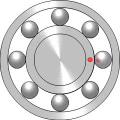
Ball Bearings
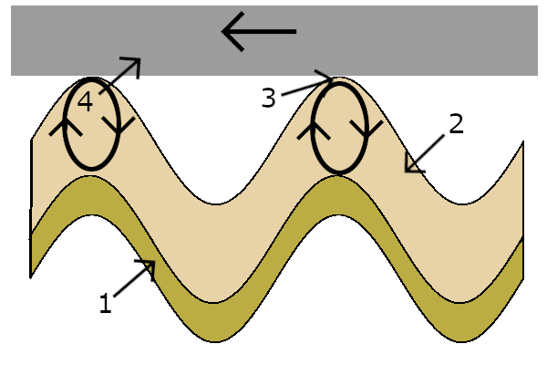
Ball bearings work by using a series of ball bearings housed in a carriage that moves along a rail or guide. The rail typically has a precision-ground track with grooves for the bearings to roll along. The carriage contains ball bearings that travel between the rail and the carriage surface, allowing for smooth, low-friction movement. As the carriage moves along the rail, the ball bearings reduce resistance and wear, ensuring precise linear motion with high load capacity and stability. This design is commonly used in applications like CNC machines, robotics, and automated systems, where high accuracy and durability are essential. A linear ball bearing consists of a polymeric cage with raceway segments made of hardened steel to guide the ball sets within the complete system. The recirculating balls provide unlimited stroke and low friction movement.
Author: PlusMinus. Unedited image.
Advantages:
- High load carrying capacity.
- High rigidity.
- Low friction.
- High positional accuracy.
- Acceleration up to 150 m/s^2.
Disadvantages:
- Lower load capacity compared to roller bearings.
- Increased sensitivity to misalignment and shock loads.
- Require constant lubrication to prevent heat buildup and degradation.
- Precision problems with light loads over short distances – can slip at accelerations over 1 G.
Applications:
- Automation & Manufacturing: Ball bearings are used for ensuring smooth and efficient movement of robotic arms, conveyor belts, and assembly lines. They reduce friction in machinery, allowing for high-speed operation and precise positioning in applications like CNC machines and packaging systems.
- Industrial Machinery: Ball bearings are used in industrial machinery, such as pumps, compressors, and motors, ensuring reliable and low-friction movement for heavy-duty tasks.
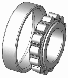
Roller Bearings
Roller Bearings use cylindrical rollers (instead of balls) to handle load distribution. These rollers roll between two races rather than sliding over them. This can provide better load capacity compared to ball bearings, especially for heavier loads. This rolling action also allows roller bearings to handle both radial and axial loads efficiently.
Author: Silberwolf. Unedited Image.
Advantages:
- High load capacity: Roller bearings can handle significantly heavier loads than ball bearings due to the load distribution being over a larger contact area.
- Minimal radial runout: The cylindrical rollers allow for more uniform contact with the raceways, minimizing the deviation from perfect circular motion.
- Reduced maintenance: Many roller bearings are available with seals that protect against dirt, moisture and fine particles. This makes them useful for semiconductor and medical equipment manufacturing.
Disadvantages:
- Larger than ball bearings, they have greater dimensional requirements.
- Sensitivity to misalignment: Improper alignment can lead to increased wear and reduced precision.
- High initial cost: They tend to be more expensive than other mechanical bearings due to their more complex design. Not ideal for cost sensitive applications.
- Thrust loads: Roller bearing can handle thrust loads, but they are less suited for pure axial load handling compared to ball bearings.
Applications:
- Automotive: In wheel hubs, transmissions, and clutch systems, where both radial and axial loads are encountered.
- Industrial Machinery: In gearboxes, conveyor systems, and heavy machinery like pumps, compressors, and turbines.
- Machine Tools: In CNC machines, spindles, and precision rotary stages where high loads and rotational accuracy are important.
- Electric Motors: In motors where high radial loads and durability are needed.
- Aerospace: In aircraft engines, landing gear, and other systems where reliability and durability are paramount.
Roller bearings are essential components in many industrial and mechanical systems, offering high load capacity, reliability, and durability under heavy-duty conditions. Their different variants—cylindrical, tapered, needle, spherical, and thrust roller bearings—are designed to meet specific needs, whether it’s for high radial load handling, axial load support, or tolerance to misalignment. While they are generally larger than ball bearings, their ability to handle higher loads makes them indispensable in demanding applications across diverse industries.
Air Bearings
Air bearings use pressurized air to create a frictionless layer between two surfaces allowing for smooth and precise motion.
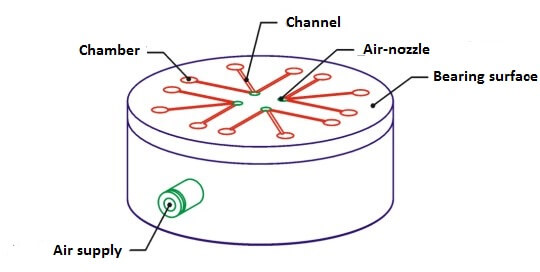
Author: Aerobearing. Unedited Image.
The basic purpose of a linear motion guideway is to eliminate, as closely as possible, five out of six degrees of freedom. The non-contact factor sets air bearings apart from conventional mechanical guideways. Air bearings provide a completely non-contact bearing ways, motor and encoder. There is no friction during movement leading to high resolution and throughput. This allows constant velocities to be achieved consistently.
The disadvantages are that there is an added cost associated with the air bearing infrastructure to provide a constant air supply. This mechanism is also susceptible to amplifier induced or environmental vibration errors. Air bearing guideways are less stiff compared to their rolling steel counterparts, this results in a lower first resonance and lower servo bandwidth. An ideal environment for air bearing use would be when frictionless motion is required with nanometer repeatability or accuracy.
For optimal performance, fluid film bearings require the gap to be small to allow pressure to build. For bearings using gases, this gap is in the order of a few microns. The bearing and mating surface geometry is usually controlled to less than one fifth of this gap. This accuracy requirement presents a manufacturing challenge.
Advantages:
- Greater precision and accuracy compared to mechanical bearings.
- High speeds can be achieved, up to 300,000 rpm with minimal heat generation and power loss.
- Spherical air bearings can simulate zero gravity environments to maintain high precision positioning.
- Travel ranges of 1 m or more are feasible.
- Minimal Eccentricity (lateral runout) and Wobble (pitch and roll).
- Improved surface finish due to repeatable motion given by air bearing spindles, for semiconductor processing applications.
Disadvantages:
- Cost increase.
- Need to provide a constant supply of clean dry air.
- Air bearing guideways are less stiff than rolling steel bearing guideways used by conventional stages.
Applications:
- Surface Finish: Improved surface finish due to repeatable motion given by air bearing spindles allows for < 0.05 micron grinding tolerances.
- EUV: Air bearings are critical for EUV chip manufacturing since they provide thermal isolation and do not eject particles into the environment.
- CMM and Metrology: Air bearings are used to guide the probe and move the sample being measured due to minimal hysteresis and reversal error.
- Air bearings spindles are used for the most demanding machine tool and inspection applications. They offer high load capacity and stiffness with low air consumption. Axial: 250 N/micron, Radial: 580 N/micron.
Want to learn more?
Address
1 Cabot Road, Suite 210 Hudson, MA 01749
Call Us
1-508-634-6688